We are authorized suppliers of Oertzen, Casuma, Woma, HPP-Comet pumps and few other European pumps. We built complete High Pressure Water Jetting Pump systems based on the requirements which includes, High Pressure Pump Selection, Design of the complete system, Recommendation of pressure requirements, motor, nozzles etc.
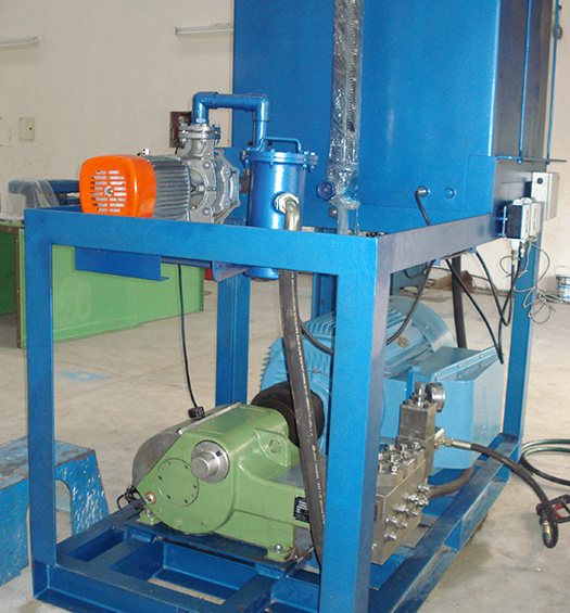
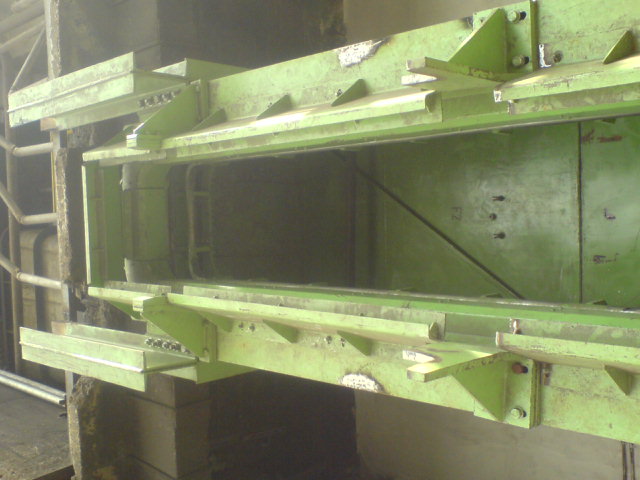
The Water Jet Door Cleaners incorporate
- Cleaner head
- Support carriage
- Spray jet carriage
- Debris catchment system
- High Pressure water pump unit
- Electrical and Hydraulic Control System
Advantages
- High efficiency in cleaning carbon and coke deposits rather than manual cleaning
- Complete protection of door seals
- Smoother door extraction and replacement
- Lower annual maintenance costs for the door
- Reliable Low Maintenance Water System
- High Performance Cleaning Nozzles
- Simple Drive System – Few Moving Parts
- Mechanical cleaning of all relevant areas of coke oven doors
- Fully automated cleaning process
- Highest cleaning efficiency
- Low maintenance
- Hydraulic systems + Electrical Control Panel
- High pressure water jet cleaning (600 Bar)
- Supplied to Tata Steel & other SAIL plants


Salient Features
Interchangeable Plunger Kit to Enable Meeting the Customer Requirement of Flow & Pressure
Pump Head In
- Stainless Steel
- Forged Steel
Plungers In
- Ceramic ( White )
- Stainless Steel
- Ceramic Coated ( Black ) Stainless Steel
Option : Pneumatically Operated Pressure Relife Valve
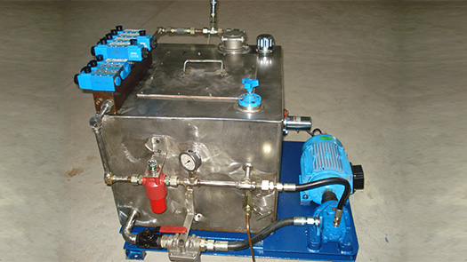
ARS Hydrojet offers a wide range of high pressure jetting system for diverse applications with pressure ranging from 25 to 750 bar and discharge from 30 to 400 lpm. The jetting system can be mounted on base frames/skids, trolleys, or on LCV/HGV chassis, or diesel driven as per the choice of the customer.
 High pressure water is primarily used as a tool in these jetting system for the various end application like descaling, cleaning, etc. where the heart of the system will be a high pressure triplex positive displacement reciprocating pump.
 Suction operation can carried out by sucking out slit, grinding sand, grinding dust with coolant water, slurry, mud, grit, wastewater, etc, from end application areas like cesspit, sewer line, septic tank, gullies.
Material can be sucked from depth up to 5 meter in conventional / standard unit fitted with sliding vane type blower. Utilizing the deep suction unit provided with a roots type exhauster the sludge material can be transported from 20 meter or more.
Specification
ARS suction unit tank capacity 1000 to 5000 liters, (customer requirement) welded steel construction with dished end front side of the tank. A level sight glass is provided for the tank. Sludge draining is also through a 100NB valve provided in front of the tank.
Filters
This unit has two filters
- Air Filter Unit
- Secondary Shut Off Unit
Air Filter Unit
Filter unit is provided with filter element. The filter unit is mainly used to remove the fine particles and moisture. It consists of one number of wire mesh / paper filters and it will observe both moisture and fine particles and allow the dust free air to enter the blower. The control filter hatch is filled with insulation to observe the noise pollution.
Secondary Shut Off Unit
The secondary shut off valve is provided between suction tank and the filter unit. This shut off valve consist of ball arrangement to control the over flow of the water. This arrangement is provided to safeguard the filter arrangement and the blower.
Control Values & Safety Devices
 All safety devices like the pressure relief valve, vacuum relief valves, compound pressure gauges, level indicators & Electrical sensor, etc., required for the safe operation of the complete system are provided at the necessary / convenient locations on the unit.
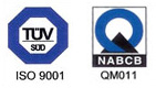
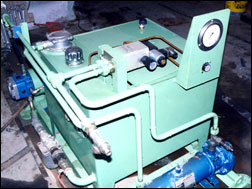
 ARS designed & supplied the Hydraulic power pack is a custom built module for operation and control of any standard or special purpose hydraulic equipment. It consists of a pump -motor unit to produce flow & pressure of Hydraulic fluid, control block to house various control elements, directional control valves and filtration components. All the components are layed out on the top of reservoir or a fabricated super structure.
Technical Data
- MOTOR POWER FROM 0.5 HP TO 50 HP.
- RESERVOIR CAPACITY FROM 10 LIT TO 1000 LITRES.
- FLOW OF FLUID HANDLED FROM 1.5 TO 300 LPM.
- MAX. OPERATING PRESSURE UP TO 350 KG/CM2.
- TYPES OF CONTROL – MANUAL, ELECTRICAL SOLENOIED, REMOTE CONTROL.
- MAKE OF HYDRAULIC VALVES & PUMPS – VICKERS, REXROTH, BOSCH, HYDAC, POLYHYDRON & YUKEN, ETC.,
 ARS also designed & supplied the hydraulic cylinder with standard design & custom built as per the customers / application requirements.
Feeder Conveyor Assembly
 Feed Conveyor feeds billets one-by-one to billet lifter device & pusher. At the start conveyor moves one full length, so that one billet is pushed to a lifting tray on same level of roller.
The Feed Conveyor is driven by Geared Motor with Chain Sprocket Arrangement. The Conveyor Will forward & Reverse facility (Electrically) is Provided . Supporting structure is provided to accommodate the feed rollers, drive unit for feed conveyor and Billet guide to guide the Billet.
Billet Handling Roller Conveyor System
The cold billets are lifted one by one from ground level of pallet/Tot box with Monorail Crane. Permanent magnet lifter attached with hook of Monorail crane and magnet lifter having UP and DOWN ,FORWARD and REVERSE, ON /OFF hand lever operation. For safety purpose of lever striker (locker) is provided. When the permanent magnet on the billet surface from the ground level, Turn the magnet lever to ON position and lock the lever. Now the Billet will be held by the magnet device.
– Normally Billet is lifted from Ground “0” level to approximate 1.00 Mt.
– The Billet lifted with Magnet Device will move to the centerline of the Conveyor and placed on the damper tray of the feed Conveyor.
Billet Extractor With Accept / Reject Device
 The hot billet comes out of the induction coil is received by the billet extractor conveyor and stopped by the stopper gate arrangements at the end of the conveyor. The Stopper is operated by the hydraulic Cylinder.
The hot billet is sensed by (HMT) temperature sensor. If the temperature is within the acceptable range the stopper plate will open and the billet is taken for next operation.
If the temperature is not within acceptable range, the billet is discarded with the help of Discarder fingers placed in between rollers of extractor. Discarder fingers are below the roller line while normal operation to avoid any obstruction. Discarder is operated by the hydraulic cylinder.
Billet Lifter Assembly
 When feed conveyor moves, one full billet comes on this tray. The Billet received from the feed conveyor to the lifter. Then the Billet is lifted by the lifter to the passing through induction Coil. Lifting cylinder speed is controlled by flow control valve, while return stroke is fast. Tray will orient the billet at induction coil in flat face position. Limit Switches are provided to control the stoke length of cylinder.
Billet Pusher
The billet is aligned along the coil, is pushed into the induction coil by pusher mechanics fixed to the feed conveyor structure. The Pusher mechanics consists of hydraulic cylinders attached with the pushing ram guided by rollers. The stroke of pusher is adjustable for various sizes/ lengths of billets so that on completion of one pushing stroke one full hot billet comes out at the out feed end of induction coil.
Damper Assembly
A damper tray having provision to move up/down 90mm vertically with help of 4 nos of guide pushes & guide rods provided at the start of rollers of feed conveyor. At the beginning of process tray remain up & billet is placed on tray in flat position. Tray goes down after receiving the billet & places it on roller feed conveyor in flat position. The Tray up/down vertical motion controlled by Hydraulic Cylinder. Limit switches provided for indication the hydraulic cylinder motion.
Billet Discharge Conveyor
 Discharge conveyor is last part of induction heater, from where billets are picked by manipulator for further process. Conveyor length is @ 1000 mm and idler roller arrangement.